
Now Reading: How To Wire A 3 Button Garage Door Opener
- 01
How To Wire A 3 Button Garage Door Opener

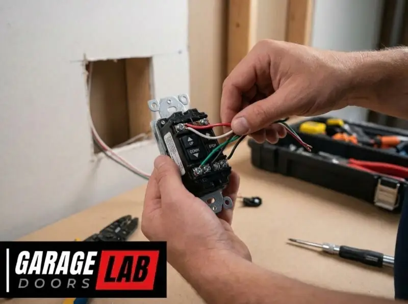
Wiring a three-button garage door opener, while a task that can be accomplished by a determined DIYer, involves working with electrical components and requires a methodical approach. Understanding the function of each button and how they connect to your garage door opener system is crucial for a successful installation or repair.
This guide will walk you through the process, covering the essential wiring aspects, common scenarios, and important safety considerations. Whether you’re replacing an old opener, adding a new control panel, or troubleshooting a faulty connection, this comprehensive overview aims to equip you with the knowledge needed to tackle the job with confidence.
Key Takeaways
- Identify Button Functions: A standard three-button opener typically controls Open, Close, and Stop/Lock functions.
- Wiring Basics: Connections usually involve low-voltage wires from the opener motor unit to the wall-mounted button console.
- Safety First: Always disconnect power to the opener before beginning any wiring work.
- Consult Manuals: Refer to your specific garage door opener’s manual for precise wiring diagrams and instructions.
- Troubleshooting: Common issues include loose connections, incorrect wiring order, or faulty buttons.
- Professional Help: If you’re uncomfortable with electrical work, hire a qualified technician.
Understanding The Three-button Garage Door Opener System
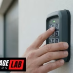
A three-button garage door opener console is a common interface that provides convenient control over your garage door’s operation. Each button is designed to perform a specific function, contributing to the overall usability and security of your garage. Understanding these functions and the underlying wiring is the first step in successfully managing your opener system.
The Role Of Each Button
Typically, a three-button opener panel features the following:
- Open Button: This button initiates the upward movement of the garage door. Pressing it once will cause the door to open fully, or to its pre-set open position.
- Close Button: This button initiates the downward movement of the garage door. Pressing it once will cause the door to close completely, or to its pre-set close position.
- Stop/Lock Button: This button serves a dual purpose. Primarily, it acts as a stop button, halting the door’s movement at any point. In some models, particularly those with enhanced security features, this button can also act as a lock button. When engaged in lock mode, it prevents the remote control or keypad from operating the opener, enhancing security when you are away.
How The System Communicates
The three-button console communicates with the main garage door opener motor unit, usually located on the ceiling of your garage. This communication is facilitated by low-voltage wiring that runs from the motor unit to the wall-mounted console. When a button is pressed, it completes a circuit, sending a specific signal to the motor unit. The motor unit then interprets this signal and executes the corresponding action. The voltage used for these control wires is typically very low, often 24 volts or less, making it relatively safe to work with compared to household AC wiring. However, safety precautions are still paramount.
Common Opener Brands And Their Wiring Conventions
While the fundamental principles of wiring are similar across brands, there can be slight variations in terminal designations and wire colors. Major manufacturers like LiftMaster, Chamberlain, and Genie all produce three-button consoles, and their manuals will provide the most accurate wiring diagrams for their specific models.
- LiftMaster/Chamberlain: These brands often use a common wiring scheme. The motor unit typically has clearly labeled terminals for “Common,” “Up,” and “Down.” The three-button console will have corresponding terminals where these wires connect. The “Stop/Lock” function might share a terminal or have its own dedicated connection depending on the model.
- Genie: Genie openers also follow a similar low-voltage wiring principle. Their consoles will have terminals labeled, and the connection points on the motor unit will correspond. It’s always best to consult the specific Genie model’s manual for precise wiring instructions.
Understanding these brand-specific nuances can save time and prevent errors during installation or troubleshooting.
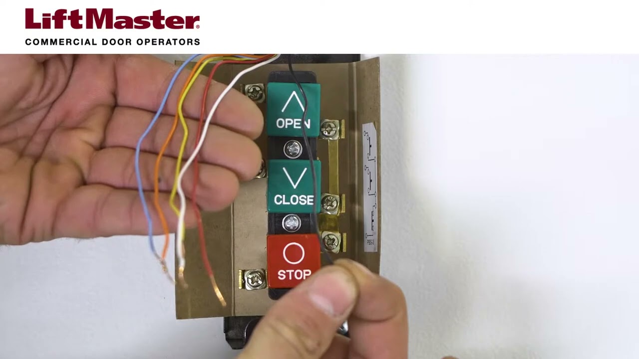
Credit: www.youtube.com
Safety First: Essential Precautions Before Wiring
Working with any electrical system, even low-voltage ones, necessitates a commitment to safety. Ignoring basic precautions can lead to electrical shock, damage to your equipment, or even fire hazards. Before you even pick up a screwdriver, ensure you have taken the appropriate safety measures.
Disconnecting Power
The absolute first step before touching any wires is to disconnect power to the garage door opener. This is typically done by:
- Locating the circuit breaker: Find the breaker that controls your garage door opener in your home’s electrical panel.
- Switching off the breaker: Flip the breaker to the “OFF” position.
- Verifying power is off: Attempt to operate the garage door using your existing remote or wall button. If nothing happens, the power is successfully disconnected.
Pro Tip: For added safety, you can also unplug the opener unit directly from its power outlet if it’s accessible and easily reachable without compromising the opener’s mounting.
Understanding Low-voltage Wiring
Garage door opener control systems operate on low-voltage circuits, which are significantly less dangerous than standard household 120V or 240V wiring. However, low-voltage wires can still carry enough current to cause minor shocks or damage sensitive electronic components if short-circuited. Always assume the wires are live until you have confirmed the power is off.
Protective Gear And Tools
- Safety Glasses: Always wear safety glasses to protect your eyes from any stray debris or accidental wire snaps.
- Insulated Tools: Use tools with insulated handles, such as screwdrivers and wire strippers. This provides an extra layer of protection against accidental contact with live wires.
- Gloves (Optional): While not strictly necessary for low-voltage work, wearing non-conductive gloves can provide additional peace of mind.
Avoiding Shortcuts And Rushing
Electrical work requires patience and precision. Never rush the process. Take your time to read instructions, identify wires correctly, and make secure connections. Cutting corners can lead to troubleshooting headaches down the line or, worse, safety hazards. If at any point you feel unsure or uncomfortable, it’s always best to stop and consult a professional.
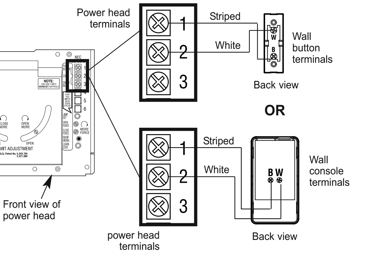
Credit: community.garadget.com
Wiring The Three-button Console: Step-by-step
This section provides a general guide to wiring a three-button garage door opener console. Always refer to your specific opener’s manual for the most accurate wiring diagram. Variations exist between manufacturers and models.
Step 1: Accessing The Motor Unit Terminals
Locate your garage door opener’s motor unit (the main box mounted on the ceiling). You’ll need to access the low-voltage terminal block where the control wires connect. This is usually a small panel or a set of screw terminals.
Step 2: Identifying The Wires
You will typically need two wires for the basic open/close function and potentially a third for the stop/lock function, depending on your console and opener model. The wires usually run from the motor unit to the wall console.
- Common Wire: This is the ground wire for the control circuit. It’s often black or white.
- Up/Down/Stop Wires: These wires transmit the signals to the motor unit. Their colors can vary widely by manufacturer (e.g., red, yellow, green, blue).
Crucially, you need to identify which wire connects to which terminal on the motor unit. Your opener’s manual will have a diagram showing this. For example, one terminal might be labeled “C” or “Common,” another “UP,” and another “DOWN.”
Step 3: Connecting Wires To The Motor Unit
- Disconnect Power: Ensure the power to the opener is OFF.
- Strip Wires: If the ends of the wires are not already stripped, use wire strippers to expose about 1/2 inch of copper at the end of each control wire.
- Connect to Terminals:
- Connect the Common wire from your console’s terminal block to the “Common” terminal on the motor unit.
- Connect the wire designated for Up operation on your console to the “Up” terminal on the motor unit.
- Connect the wire designated for Down operation on your console to the “Down” terminal on the motor unit.
- If your console has a separate terminal for Stop/Lock, connect the corresponding wire to the appropriate terminal on the motor unit. Some systems combine the stop function with the up or down circuit, so consult your manual.
Important: Ensure the connections are secure. The bare copper wire should be wrapped firmly around the screw terminal and the screw tightened down. Loose connections are a common cause of malfunction.
Step 4: Connecting Wires To The Wall Console
Now, you need to connect the other ends of these wires to the corresponding terminals on the three-button wall console.
- Access Console Terminals: Open the wall console to expose its terminal block.
- Match Terminals: This is where your manual is essential. The console will have terminals labeled for “Common,” “Up,” “Down,” and possibly “Stop/Lock.”
- Connect the wire coming from the motor unit’s “Common” terminal to the “Common” terminal on the console.
- Connect the wire coming from the motor unit’s “Up” terminal to the “Up” terminal on the console.
- Connect the wire coming from the motor unit’s “Down” terminal to the “Down” terminal on the console.
- Connect the wire for the “Stop/Lock” function, if applicable, to its corresponding terminal on the console.
Example: If your motor unit has terminals C, UP, and DOWN, and your console also has terminals labeled C, UP, and DOWN, you would connect:
- Wire from Motor Unit C -> Console C
- Wire from Motor Unit UP -> Console UP
- Wire from Motor Unit DOWN -> Console DOWN
Step 5: Testing The System
- Double-Check Connections: Visually inspect all connections to ensure they are secure and correctly matched.
- Restore Power: Go back to your electrical panel and switch the circuit breaker for the garage door opener back to the “ON” position.
- Test Buttons:
- Press the Open button on the console. The door should begin to open.
- Press the Close button. The door should begin to close.
- While the door is moving, press the Stop button. The door should halt its movement.
- If your system has a lock function, test that feature according to your manual’s instructions.
If the system doesn’t work as expected, do not panic. The next section covers common troubleshooting steps.

Credit: www.youtube.com
Troubleshooting Common Wiring Issues
Even with careful installation, wiring problems can arise. Fortunately, most issues with three-button opener wiring are relatively straightforward to diagnose and fix. The key is to approach troubleshooting systematically.
Issue 1: Opener Does Not Respond To Any Button
This is often the most frustrating issue, but it usually points to a fundamental connection problem.
- Check Power: Is the opener receiving power? Check the circuit breaker and the outlet.
- Verify Wire Connections at Motor Unit: Are the wires securely attached to the correct terminals (Common, Up, Down) on the motor unit? Are any wires loose or disconnected?
- Verify Wire Connections at Console: Are the wires securely attached to the correct terminals on the wall console?
- Check for Damaged Wires: Inspect the entire length of the control wire for any nicks, cuts, or damage that could cause a short circuit or break in the connection.
- Faulty Console: In rare cases, the console itself might be defective.
Issue 2: Only One Button Works (e.g., Open Works, Close Doesn’t)
This usually indicates a problem with the specific wire or terminal for the non-functioning button.
- Focus on the Non-Working Button: If the “Close” button doesn’t work, examine the wire connecting the “Down” terminal on the motor unit to the “Down” terminal on the console.
- Check Connections: Ensure the wire is firmly connected at both ends.
- Inspect Wire: Look for damage specifically on the wire associated with the faulty function.
- Terminal Issues: The terminal itself on either the motor unit or the console might be damaged or corroded.
Issue 3: Opener Works Intermittently
Intermittent issues are often caused by loose connections.
- Tighten All Terminals: Go back and systematically tighten every screw terminal on both the motor unit and the console. Even a slight looseness can cause intermittent operation.
- Wire Strain: Ensure wires are not being pulled or strained, which can loosen connections over time. Use cable staples or ties to secure the wiring neatly.
- Environmental Factors: Extreme temperatures or moisture can sometimes affect electrical connections, though this is less common with low-voltage systems.
Issue 4: Stop/lock Button Malfunctions
If the stop button doesn’t halt the door, or the lock function doesn’t work, the issue is likely specific to that particular wire or terminal.
- Consult Manual: This function can be wired differently across models. Refer to your manual to confirm the correct wiring for the stop/lock feature.
- Check Specific Connections: Inspect the wire and terminals dedicated to the stop/lock function.
- Console Defect: The button mechanism within the console itself might be faulty.
Using A Multimeter For Advanced Troubleshooting
If visual inspection and tightening connections don’t resolve the issue, a multimeter can be invaluable for diagnosing electrical problems.
- Continuity Test: With the power OFF, you can use a multimeter set to continuity mode to test if a wire is unbroken. Place the probes on each end of a wire; if it beeps (or shows near-zero resistance), the wire is good.
- Voltage Test: With the power ON (and extreme caution exercised), you can test if voltage is reaching the correct terminals when a button is pressed. This requires understanding the expected voltage levels for your specific opener.
Warning: Using a multimeter on live circuits should only be done by individuals with a solid understanding of electrical safety and testing procedures. If you are not comfortable, do not attempt this.
Replacing An Existing Three-button Console
Sometimes, you might need to replace an old or damaged three-button console. The wiring process is essentially the same as installing a new one, but you’ll be disconnecting an old unit first.
Step 1: Document The Existing Wiring
Before disconnecting anything, take clear photos of the current wiring connections on both the motor unit and the old console. Note which wire color goes to which terminal. This is your most valuable reference.
Step 2: Disconnect Power
As always, turn off the power to the garage door opener at the circuit breaker.
Step 3: Remove The Old Console
Carefully detach the old wall console from the wall. Unscrew any mounting screws and gently pull it away. You should now have access to the wires connected to its terminals.
Step 4: Disconnect Wires From The Old Console
Loosen the terminal screws and carefully remove the wires from the old console. Keep track of which wire was connected where.
Step 5: Connect The New Console
Follow the steps outlined in the “Wiring the Three-Button Console: Step-by-Step” section, using your documented photos and the new console’s manual to connect the wires to the correct terminals. Ensure all connections are secure.
Step 6: Test The New Console
Once wired, restore power and test all functions of the new console to ensure it operates correctly.
Integrating A Three-button Console With Different Opener Types
While the wiring principles remain consistent, the specific implementation might vary slightly depending on the type of garage door opener you have (e. g. , chain drive, belt drive, screw drive) and its age.
Older Vs. Newer Openers
- Older Openers: May have simpler terminal blocks. The wiring might be more straightforward, often using basic screw terminals. The “Stop” function might be integrated differently, sometimes requiring a specific sequence of presses or a dedicated button.
- Newer Openers: Often feature more sophisticated control boards with clearly labeled, sometimes push-in, terminals. They may have more advanced security features, like the lock function, which requires a specific connection. Newer models also often integrate Wi-Fi or smart home capabilities, though these do not typically affect the basic three-button wiring.
Compatibility Considerations
- Universal Remotes and Keypads: If you’re using a universal remote or keypad system, the wiring might differ. These systems often have their own receiver units that need to be wired into the opener’s system, usually by connecting to the same terminals as a standard wall button.
- Security+® Technology: LiftMaster’s Security+® rolling code technology is standard on most modern openers. The three-button console works in conjunction with this system, sending unique codes each time it’s used. The wiring itself doesn’t change due to the rolling code technology, but ensuring the opener and remotes are properly paired is crucial. You can learn more about pairing and resetting these devices by checking out guides on how to reset Liftmaster garage door opener remote.
Wireless Options
It’s worth noting that many modern garage door openers offer wireless keypads and even smartphone control. While this article focuses on wired installations, wireless solutions eliminate the need for running wires through walls and attics, simplifying installation significantly. However, for a permanent, reliable control point inside the garage, a wired three-button console remains a popular and effective choice.
Data And Statistics On Garage Door Opener Usage
Garage door openers are a ubiquitous part of modern homes, enhancing convenience and security. Understanding their usage patterns and the technology behind them can provide context for why reliable wiring is so important.
According to a Statista report, the penetration of automatic garage door openers in US households has been consistently high, with estimates often placing it above 85%. This widespread adoption highlights the reliance consumers place on these devices for daily access.
The market for garage door openers is substantial, with industry reports indicating millions of units sold annually in North America alone. This sustained demand underscores the importance of accessible and reliable installation and maintenance information.
The technology powering these openers has also evolved. Early models relied on simple fixed codes, making them susceptible to “code grabbing.” Modern systems, like those employing rolling codes, significantly enhance security. The three-button console remains a fundamental interface, regardless of these technological advancements, making its correct wiring a constant requirement.
Comparing Wiring Approaches: Wired Vs. Wireless
When considering how to control your garage door, the choice between a wired three-button console and a wireless system is a key decision. Each has its own set of advantages and disadvantages.
Wired Three-button Console
| Feature | Description | Pros | Cons |
|---|---|---|---|
| **Installation** | Requires running low-voltage wires from the motor unit to the console location. | **Reliable connection**, no battery changes needed, often more durable. | **More complex installation**, requires drilling/fishing wires, can be time-consuming. |
| **Power Source** | Powered directly by the opener motor unit via the control wires. | No batteries to replace or worry about. | If the opener loses power, the console won’t function. |
| **Functionality** | Typically offers Open, Close, and Stop/Lock functions. | Direct, instant response. | Limited to pre-defined button functions. |
| **Security** | Secure connection as long as wires are not tampered with. | Generally considered very secure for internal access. | Wires could potentially be cut if accessible from outside (rare). |
| **Cost** | Console units are generally inexpensive. Installation cost can be higher if hiring a professional. | Low cost of the unit itself. | Potential labor costs for running wires. |
| **Maintenance** | Minimal; mainly ensuring connections remain tight. | Very low maintenance. |
Wireless Keypads/remotes
| Feature | Description | Pros | Cons |
|---|---|---|---|
| **Installation** | No wires needed; unit is typically mounted near the garage door. | **Easy installation**, no drilling or wire fishing required, quick setup. | **Requires battery changes**, potential for signal interference, less robust than wired connections. |
| **Power Source** | Operates on batteries (e.g., 9V, AA, coin cells). | Can be installed anywhere within range, independent of opener power. | Batteries can die unexpectedly, requiring replacement. |
| Functionality | Varies greatly; can include multiple buttons, programmable codes, temporary access codes, vacation lock. | Highly versatile